
Toe Kick Vent: When a Cover Is Not Enough
A 2.25-by-12-inch opening can pair with a 3.5-by-14-inch face. Plan the concealed route first, then verify fit, airflow, damper access and service space.
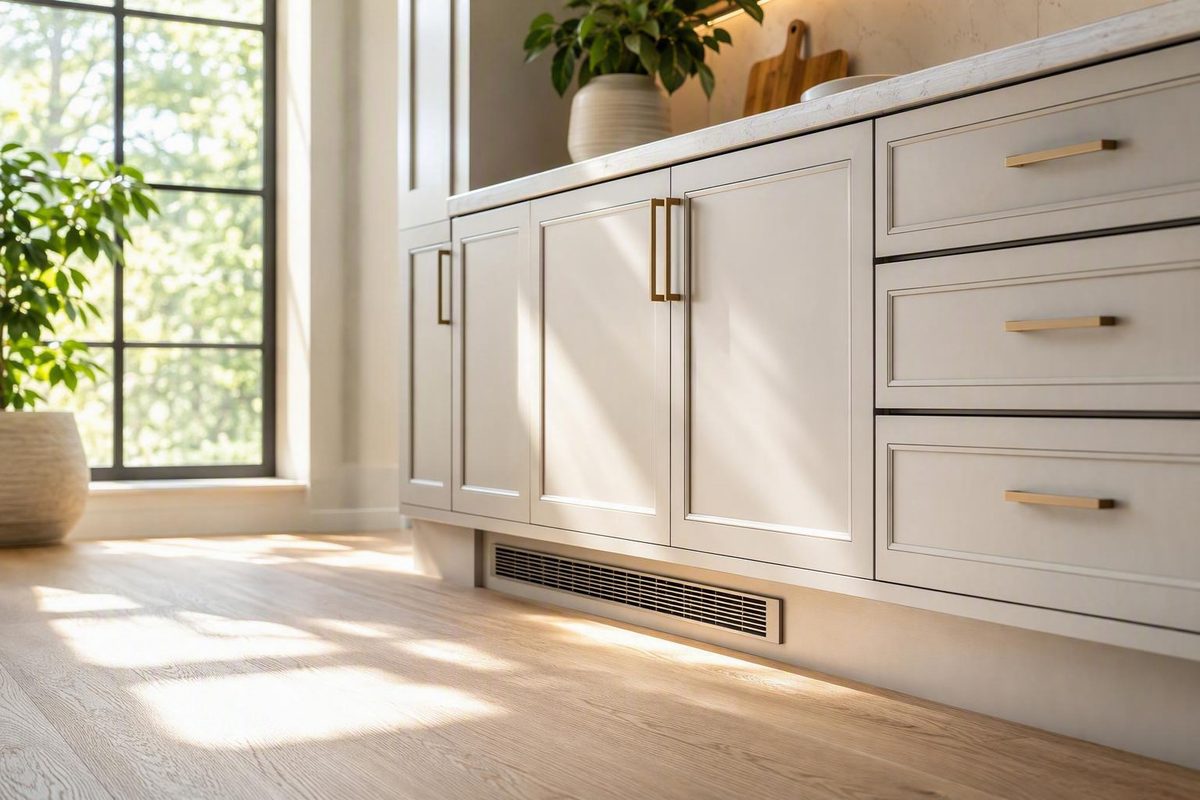
A toe kick vent looks simple from the room: a narrow grille in the recessed strip beneath a cabinet. The important work, however, happens behind that grille. Conditioned air must travel from the existing HVAC branch through a suitable transition and across a shallow, sometimes obstructed cabinet base before reaching the outlet.
That distinction should guide the entire project. A decorative cover may finish an opening that is already connected to sound ductwork, but it does not create the concealed air path. Depending on the installation, the complete assembly may require a boot, low-profile duct, custom transition, damper, protected chase, fasteners, and suitable duct sealant.
Begin by documenting the existing supply, cabinet construction, available space, and any uncertainty about required airflow. Choose a routing concept next. Measure the rough opening and exterior-face clearance only after the route is understood, then select a grille or register that fits the complete assembly.
By Ellen Marsh, whose experience includes eleven years drafting kitchen plans for a cabinet manufacturer. This article addresses cabinet coordination, measurement, and product selection. It is not an HVAC load calculation, code determination, or substitute for project-specific mechanical review.
What a toe-kick HVAC outlet is—and what each component does
The cabinet toe kick is the recessed area at the bottom of a base cabinet or built-in. It gives a person’s feet room beneath the cabinet when standing at the counter. When cabinetry covers an HVAC supply, air may be redirected beneath the cabinet and discharged through an opening in the front toe-kick panel.
Toe-kick outlets appear in kitchens, bathrooms, laundry cabinetry, vanities, window seats, booths, bookshelves, and other built-ins. Those applications do not share a universal configuration. Cabinet bases, moisture exposure, finish-panel thickness, clearances, and access vary from one project to another.
Product terminology can also be inconsistent:
-
Vent is a broad term for an opening through which air enters or leaves an HVAC system.
-
Register usually combines a grille with a damper that can regulate airflow.
- Decorative cover or faceplate emphasizes appearance and may not include a damper, boot, adapter, or duct connection.
RectorSeal’s register guide similarly distinguishes a register with a damper from the broader term “vent.” It also explains that register size normally refers to the duct opening, not the larger exterior face dimensions of the cover in its guide to register terminology and measurement.
A complete toe-kick supply assembly may include:
- Original supply opening or branch connection: The floor, wall, baseboard, round duct, or rectangular boot from which the air begins.
- Boot or transition: A fitting that changes the source opening’s shape, dimensions, direction, or elevation.
- Under-cabinet duct or chase: The air path carrying the supply across the cabinet base.
- Toe-kick rough opening: The cutout in the front panel through which air enters the room.
- Grille or register: The visible component covering the rough opening.
- Damper: A control for adjusting airflow, incorporated into the register or installed elsewhere in the route.
- Fasteners and sealant: Products selected for the particular fittings and assembly.
- Protective enclosure or insulation where specified: Components that may be required by the product instructions or project conditions.
These dimensions are related but not interchangeable. The original floor opening may be much larger than the final toe-kick cutout. A transition may require more depth than either opening suggests. The cover’s exterior face must overlap the rough opening while fitting within the recess without striking the floor, doors, trim, or appliance panels.
A faceplate that fits the cabinet does not prove that the outlet will deliver the required airflow. This guide therefore focuses on configuration, measurement, purchasing, and professional-review triggers rather than prescribing a universal duct or register size.
Start with the existing supply, not the decorative cover
The first planning decision is not the grille pattern or finish. It is how the existing—or proposed—HVAC branch will reach the toe kick.
Identify the source location
Place the project into one of four categories:
- Floor supply beneath the cabinet: The branch already terminates in the floor area the cabinet will cover. The route must usually change direction and cross the cabinet base.
- Wall supply concealed by cabinetry: The route must turn from the wall into or beneath the base and then toward the front panel.
- Baseboard supply being covered: The replacement route must account for the original wall-level or floor-level geometry rather than simply blocking the outlet.
- Proposed new branch: The project involves HVAC design as well as cabinet coordination. Branch capacity, room airflow, damper placement, and system balance should be resolved before cabinet cuts are finalized.
Record the source opening’s width and length—or diameter—along with its orientation, elevation, and distance from the proposed toe-kick outlet. Photograph the opening with a tape measure visible. Note whether the source is a boot, bare duct end, former floor-register opening, or another configuration.
Identify the cabinet-base construction
Next, inspect what will surround the route:
- An enclosed platform base may offer a predictable cavity, but enclosure alone does not establish that the space is suitable as an HVAC plenum.
- An open cabinet base provides no defined route from the supply to the grille.
- A separate toe-kick platform may allow a purpose-designed duct or enclosure to be installed before cabinet boxes are set.
- Adjustable legs or levellers generally create an elevated, open space behind a removable finish panel.
- An already-installed cabinet may offer access only from the front, cabinet interior, basement, or crawl space.
Coordinate this investigation with the broader cabinet and toe-kick dimensions used in the room plan. The HVAC route must fit the actual cabinet base, not an assumed empty rectangle.
An open, elevated, or difficult-to-seal base points toward a directly connected duct or protected chase. Releasing air into the general space beneath the cabinet and expecting it to find the grille creates avoidable uncertainty about where the air will go.
Choose the correct purchasing category
| Category | Appropriate starting point | What it does not solve by itself |
|---|---|---|
| Replacement grille or register | An existing toe-kick opening is already connected to sound ductwork | Missing, leaking, or unsuitable routing |
| Conventional boot and flat duct | A direct route can be assembled from compatible standard fittings | Unusual offsets or highly constrained geometry |
| Custom sheet-metal transition or chase | Standard parts cannot accommodate the source, offset, or available clearance | Airflow sizing and system-balance questions |
| Purpose-built routing kit | The measured source and cabinet arrangement match the kit’s documented configurations | Universal compatibility or guaranteed airflow |
Toe Ductor, for example, offers separate approaches for floor, wall, and baseboard conversions. The manufacturer lists compatibility with 4-by-10-inch, 4-by-12-inch, and 6-inch-round supplies on its product page. Those are manufacturer compatibility statements for particular products, not universal toe-kick dimensions.
Before ordering, document:
- Source location and dimensions
- Branch shape and orientation
- Distance and offsets to the toe kick
- Cabinet-base construction
- Available height, depth, and width
- Proposed rough opening
- Damper location
- Access for assembly, sealing, adjustment, and service
- Required room airflow, if known
This information determines whether the project needs only a cover, an adjustable register, a standard transition, or a complete routing assembly.
How to measure the opening, recess, and cover
Toe-kick products may be labeled by nominal opening size even though their visible faces are larger. Measure the source opening, proposed outlet, surrounding recess, and connection space separately.
Use this worksheet before ordering:
| Measurement | What to record | Why it matters |
|---|---|---|
| Existing supply opening | Width × length, or diameter | Determines the source connection or adapter |
| Source orientation | Direction, position, and elevation | Reveals required turns and offsets |
| Planned toe-kick rough opening | Exact width × height | Must match the selected product specification |
| Toe-kick height | Floor to underside of cabinet or panel limit | Controls maximum cover and route height |
| Recess depth | Cabinet face to toe-kick panel | Affects visibility, access, and collision risk |
| Available face width | Clear horizontal panel space | Prevents overlap with seams, legs, trim, or appliances |
| Cover outside dimensions | Full visible width × height | Confirms that the face fits the recess |
| Mounting-hole clearance | Hole positions and sound material around them | Determines whether the cover can be secured |
| Cabinet-floor clearance | Space above the proposed route | Determines whether the transition or duct fits |
| Connection depth | Space behind the panel | Allows for collars, dampers, fasteners, and turns |
| Nearby obstructions | Levellers, blocking, utilities, flooring, and trim | May prevent installation despite a fitting cutout |
Remove an existing register before measuring its duct opening. Do not measure the old cover and assume that its exterior dimensions represent the duct size. If no toe-kick cutout exists, use the selected product’s drawing to establish the rough opening rather than tracing the outside face.
One documented decorative cover demonstrates the difference. Its 2.25-by-12-inch opening is paired with an exterior face measuring 3.5 by 14 inches. The same product family lists 2.25-inch-high openings in lengths of 10, 12, 14, 18, 24, and 30 inches, each with a larger exterior face in the manufacturer’s dimensional options. These are examples from one product line, not cabinet or HVAC standards.
A community-forum moderator has described 2-by-12-inch toe-kick registers as common. That observation is anecdotal, not a recommendation that the size will fit or provide adequate airflow for a particular branch in the forum discussion about toe-kick register size.
Check the complete face envelope
Draw the proposed cover’s full exterior rectangle on the toe-kick panel, including its mounting holes. Check for interference with:
- Cabinet doors and drawer fronts
- The floor and floor trim
- Decorative toe-kick molding
- Dishwasher, refrigerator, or range panels
- Cabinet legs, levellers, rails, or blocking
- Seams between removable toe-kick panels
- Fasteners already holding the panel
- The boot, collar, or connector behind the opening
A grille may fit the rough opening but still be unusable because its exterior flange is too tall for the recess. A cover may also fit visually while leaving no sound material for its mounting screws.
Consult the current drawing for the exact model, size, material, and options before cutting. Category filters and nominal labels may omit exterior dimensions, mounting-hole positions, face thickness, bevels, or damper depth.
For a nonstandard opening, investigate a compatible adapter, custom register, or professionally fabricated transition. Do not enlarge an opening until the concealed duct connection, cabinet structure, available route, and airflow implications have been evaluated.
Register dimensions are not airflow ratings
Physical fit is only one part of toe-kick register selection. Several quantities that sound similar describe different characteristics:
- Nominal opening dimensions: The width and height used to identify the duct opening or register.
-
Nominal face area: Width multiplied by height without subtracting blades, frames, patterns, or dampers.
-
Target airflow: The intended air volume, commonly expressed in cubic feet per minute.
The limited arithmetic is straightforward: a 2-by-12-inch rectangle has 24 square inches of nominal area, while a 4-by-10-inch rectangle has 40 square inches as compared in this register-sizing discussion.
Those figures do not establish airflow capacity. Actual performance also depends on the grille pattern, blade angle, damper position, free area, source duct, transition shape, route length, bends, leakage, system pressure, and operating conditions.
A 2-by-12-inch toe-kick outlet therefore should not be assumed to replace a 4-by-10-inch floor register merely because a transition can physically connect the two. Even products with the same nominal dimensions may perform differently if their patterns, dampers, or free areas differ.
When evaluating a product, request or look for:
- Tested free area
- Pressure-drop data at relevant airflow rates
- Recommended airflow range
- Throw or air-pattern information
- Sound data
- Damper characteristics
- Tested connection and installation configuration
If those data are unavailable, acknowledge the uncertainty rather than estimating capacity from face size. Seller descriptions such as “strong airflow” or “efficient distribution” are not substitutes for performance data applicable to the proposed assembly.
Seek qualified HVAC review when:
- The room’s airflow requirement is unknown.
- The existing branch already feels weak.
- The outlet is being reduced substantially.
- The route is long or contains several turns.
- Multiple outlets share the branch.
- Product pressure-drop or free-area data are unavailable.
- The completed system may need balancing.
There is no defensible universal toe-kick grille or duct size without project-specific airflow, pressure, and route information.
Compare the four under-cabinet routing approaches
The appropriate routing method depends on source geometry, cabinet construction, access, and required performance.
1. Dedicated flat duct or protected chase
A dedicated route connects the existing branch to a low-profile rectangular duct or purpose-built chase that terminates at the toe-kick register. This keeps the air path separate from the surrounding cabinet cavity.
It is the cautious starting point when the cabinet stands on legs, has an open base, contains gaps between components, or cannot be enclosed and examined reliably. A defined route also makes the intended air path easier to understand during installation and future service.
Forum contributors have reported using 3.25-by-10-inch and 3.25-by-12-inch rectangular duct beneath cabinets in a discussion of under-cabinet duct and plenum approaches. These are examples of reported field practice, not universal specifications or evidence that either size suits a particular branch.
A dedicated duct still requires compatible transitions and adequate clearance. Poor alignment, abrupt reductions, crushed sections, excessive bends, or an inaccessible damper can undermine an otherwise sensible route.
2. Conventional or custom sheet-metal boot
A boot changes the direction, shape, or dimensions of the source connection. Standard fittings may work when the supply is near the front panel and aligned favorably. Custom sheet metal may be appropriate when the project includes:
- An unusually shaped or offset floor opening
- Very shallow clearance
- A pipe or cabinet member near the direct route
- A supply located off-center from the proposed grille
- A transition shape unavailable as a standard fitting
Custom fabrication allows the transition to match the measured space, but it requires accurate dimensions and compatible, secure connections. It does not eliminate airflow, pressure-loss, sealing, or access questions.
3. Deliberately designed and verified sealed plenum
A sealed cabinet-base plenum uses an intentional enclosure as part of the air path. That is materially different from allowing air to spill into an open cavity.
Before considering this approach, verify the proposed enclosure’s boundaries, joints, penetrations, materials, access, connection to the grille, and suitability for the HVAC application. A platform that appears enclosed from the room may still contain gaps around walls, shims, legs, utilities, or adjacent cabinets.
Appearance alone cannot establish whether the arrangement is suitable or permitted. Check the relevant product instructions and obtain project-specific guidance from the qualified professional or authority responsible for the work.
4. Proprietary rerouting kit
A purpose-built kit may package transitions, connectors, and outlet components for a documented range of floor, wall, or baseboard supplies. It can reduce the need for custom fabrication when the measured source and cabinet arrangement match the kit.
Confirm:
- Listed source-opening dimensions
- Required clearances
- Intended route geometry
- Included register or required separate faceplate
- Connector type
- Damper provision
- Extension requirements
- Installation and sealing instructions
- Access needed during cabinet installation
Do not treat manufacturer claims of superiority, efficiency, or easier installation as independently established without comparative testing. A kit is appropriate only when its documented configuration matches the actual source, cabinet, and performance requirements.
Why open-cavity discharge deserves caution
When a supply terminates beneath a cabinet without a connected route, air may escape through gaps instead of leaving through the toe-kick grille. Possible consequences reported by building-science practitioners include reduced delivery to the room, leakage into unintended areas, pressure effects, and moisture concerns where cold supply air passes beneath a sink cabinet.
Energy Vanguard documents an unconnected toe-kick register and distinguishes that arrangement from a protected sheet-metal duct, while discussing possible leakage, comfort, pressure, and moisture consequences in its building-science account. The example does not prove that every imperfect cavity will produce every outcome, but it supports treating an open cavity cautiously.
Use a directly connected route when the base is open, elevated, unsealed, inaccessible for inspection, or otherwise unlikely to contain supply air reliably. Verify acceptable duct materials, sealing products, cavity use, and access requirements for the specific assembly rather than assuming cabinet components can serve as ductwork.
Plan new cabinetry and retrofits differently
New cabinetry allows routing and access decisions to be made before countertops, plumbing, appliances, and finish panels restrict the work. A retrofit begins with investigation because the intended route may already be blocked or inaccessible.
New cabinetry
Coordinate the following before setting the cabinet base:
- Existing or proposed supply location
- Boot and transition geometry
- Low-profile duct or protective chase
- Cabinet-floor clearance
- Toe-kick rough opening
- Finish-panel thickness and attachment
- Grille exterior dimensions
- Damper location and adjustment access
- Joint-sealing sequence
- Inspection or service access where applicable
- Cabinet installation order
Choose the toe-kick style early. A recessed panel, flush furniture-style treatment, separate platform, or cabinet on levellers creates different panel and cavity conditions. The finish detail may determine whether the grille can sit flat, whether its screws have support, and whether the route can be installed before the cabinet box is lowered into position.
The HVAC route, cabinet platform, flooring, plumbing, and appliance spaces must all describe the same finished condition. A floor boot positioned correctly for an empty room may become difficult to use once a sink base, dishwasher, or cabinet divider is installed.
Existing cabinetry
For a retrofit, assess access instead of assuming a standard procedure. If a basement or crawl space is available, inspect the source and proposed connection from below. Determine whether the transition can be attached securely without disturbing the cabinet and whether the completed connection can be checked.
Access from below may reduce cabinet demolition, but it does not guarantee a workable route. Joists, floor layers, plumbing, wiring, cabinet construction, and tool clearance may prevent the intended connection. Temporary removal of the cabinet floor may still be necessary in some configurations.
A discussion of an installed sink-base retrofit considered basement access, temporary removal and replacement of the cabinet floor, possible joist interference, and the placement of a damper in the retrofit-planning thread. These are user-generated suggestions rather than a universal installation method.
Pre-cutting obstruction checklist
Before making an opening, locate or verify:
- Floor joists and structural framing
- Drains and traps
- Hot and cold water lines
- Electrical wiring and junctions
- Other utility lines where present
- Appliance feet, panels, hoses, and electrical connections
- Finish-floor thickness
- Underlayment and subfloor layers
- Existing screws, nails, clips, and blocking
- Cabinet legs and levellers
- Drawer slides or interior hardware
- Tool body, blade, and turning clearance
- Space to attach and seal the final connection
Reported retrofit discussions include a PVC drain partly obstructing a proposed opening, a floor assembly consisting of 3/4-inch subfloor and 3/4-inch hardwood, and limited clearance for positioning cutting tools in one under-cabinet retrofit discussion. Such examples do not predict every installation, but they show why locating the grille on the visible panel is not enough.
If the intended path is blocked, alternatives may include moving the outlet, commissioning a custom offset transition, retaining or enlarging a viable floor outlet after HVAC assessment, or revising the cabinet plan. Do not alter structural framing or utilities merely to preserve a preferred grille position without appropriate project-specific review.
Plan damper access and future service at the same time as the route. A concealed damper that cannot be adjusted has limited practical value, and a critical connection should not be buried before any applicable inspection or access expectations are understood.
Choose the faceplate by function, environment, and verified fit
Once the concealed route and rough opening are established, select the visible grille or register. No single material is categorically best.
Steel
Steel covers are sold in utility and decorative patterns with painted or plated finishes. They can coordinate with dark hardware, stainless-look accents, or painted toe kicks.
Check the exact product’s coating, edge treatment, thickness, mounting method, and cleaning instructions. If the cover will be painted, verify that the selected version is designated as paintable.
Aluminum
Aluminum is available in decorative and relatively simple designs. Its suitability should be evaluated from the exact product instructions and expected exposure rather than from material name alone.
One seller describes a listed aluminum cover as rust-proof and suitable for bathrooms. The same seller permits painting designated gray steel or aluminum versions with paint intended for metal and advises against latex paint. These are product-specific seller claims and instructions, not an independent corrosion comparison. Follow the current directions for the exact model purchased.
Wood
Wood can coordinate closely with cabinetry when species, grain, stain, and finish are selected together. Check whether the cover is supplied finished or unfinished, how it mounts, and how its thickness affects the recessed face.
Do not infer airflow performance from the fact that a cover is made from wood. Performance depends on the specific pattern, free area, geometry, and any damper behind it.
ABS or other plastic
Verify environmental limitations, cleaning-product compatibility, paintability, mounting requirements, and compatibility with the selected duct or kit.
Material labels alone do not establish airflow, durability, or suitability for a particular exposure.
Decorative patterns and performance
The available product evidence does not provide independent pattern-by-pattern testing, so appearance should not be used as a proxy for performance.
If performance data are unavailable, prioritize clear dimensional documentation and ask the manufacturer for free-area and pressure-drop information. Seller-hosted ratings, testimonials, and zero-review pages are not independent evidence of airflow, fit, reliability, or installation ease.
Budget for the complete assembly
Prices vary widely with size, material, finish, decorative pattern, and whether the product is only a cover or a complete routing kit. Because the available seller captures do not include reliable observation dates, precise historical prices are not presented here as a current buying benchmark.
Budget for the whole assembly, which may include:
- Custom sizing
- Beveled edges or special finishes
- Extension components
- Separate register plates
- Dampers
- Standard or custom boots
- Custom sheet-metal fabrication
- Duct or chase materials
- Compatible sealants and fasteners
- Protective enclosures or specified insulation
- Cabinet alteration and refinishing
- HVAC and cabinet-installation labor
- Shipping, taxes, and lead-time effects
A low-cost grille does not make the overall project inexpensive if the source requires a complicated custom route. Recheck current dimensions, availability, options, lead times, and total delivered price immediately before ordering.
Use a final planning, installation, and handoff checklist
A written checklist helps keep decorative selection from getting ahead of the HVAC and cabinet work.
Before ordering
Record and confirm:
- Existing supply location, shape, and dimensions
- Existing branch condition
- Required room airflow, if known
- Cabinet-base construction
- Route length and number of offsets
- Exact toe-kick rough opening
- Toe-kick height and recess depth
- Cover exterior dimensions
- Mounting-hole positions and clearance
- Cabinet-floor and connection clearance
- Damper location
- Moisture and cleaning exposure
- Installation and future service route
- Current product drawings and specifications
If the room’s airflow requirement is unknown or the existing supply already performs poorly, pause before selecting a smaller outlet.
Before cutting
Locate:
- Structural framing
- Plumbing and drains
- Wiring and other utilities
- Appliances and service connections
- Flooring and subfloor layers
- Cabinet hardware, levellers, and blocking
- Fasteners hidden in the cutting area
- Tool-access limitations
- The complete route needed to make the connection
Confirm the cutout against the exact product drawing rather than relying only on the nominal label.
Before installation
Verify compatibility among:
- Branch duct
- Boot or transition
- Connector
- Under-cabinet duct, chase, or verified enclosure
- Toe-kick opening
- Grille or register
- Damper
- Fasteners
- Sealant
- Protective chase or insulation where specified
Dry-check the full component envelope before the cabinet or finish panel limits access. Confirm that the damper can be reached and that mounting screws will engage suitable material without contacting concealed services.
After installation
Check that:
- Air exits through the intended grille rather than obvious gaps in accessible cabinet areas.
- The grille and route do not rattle.
- The outlet does not produce excessive or newly objectionable noise.
- The damper remains accessible and operable.
- Doors, drawers, appliance panels, and removable toe kicks still function.
- Room comfort is compared with the prior condition.
- Connections remain available for any inspection required by the project.
Where suitable instruments and expertise are available, have delivered airflow checked and determine whether system balancing is needed.
For cooling systems operating in humid conditions, particularly near sink cabinetry, monitor accessible areas for condensation. Moisture is not inevitable, but cold air, plumbing exposure, and an imperfectly contained route justify attention.
Professional HVAC involvement is prudent when target airflow is unknown, the branch is weak, the outlet is being reduced substantially, a custom transition is required, the route is difficult to seal, important connections will become inaccessible, condensation is a concern, multiple outlets may interact, system balance may change, or local requirements are unclear.
The governing principle is simple: solve and verify the concealed air path first. Select the decorative face only after the route, fit, airflow uncertainty, and service requirements are understood.
Frequently asked questions
Can I put a cabinet over an existing floor vent and add a grille to the toe kick?
Potentially, but the grille alone is not enough. The floor supply generally needs a suitable route to the toe-kick outlet. Depending on the configuration, that may be a boot and flat duct, a custom transition, a deliberately designed and verified plenum, or a compatible routing kit.
Document the floor opening, branch orientation, cabinet-base construction, route clearance, damper access, and proposed outlet before placing the cabinet. If the conversion substantially narrows the outlet or adds several bends, obtain HVAC review before finalizing it.
What size toe-kick register do I need?
Choose the physical size from the required rough opening and available exterior-face clearance. Measure the duct opening, toe-kick height, recess depth, usable panel width, connection space, and mounting clearance, then check the exact product drawing.
Physical fit does not answer the airflow question. Adequacy also depends on required airflow, free area, pressure loss, route geometry, and available system pressure. Do not assume that a smaller toe-kick outlet is equivalent to the larger floor register it replaces.
Can the open space beneath a cabinet be used as the air duct?
Do not assume that it can. An open cavity may contain gaps around walls, legs, shims, utilities, and adjacent cabinets, allowing air to escape somewhere other than the grille.
A deliberately designed, enclosed, and sealed plenum is different from an open cabinet base. Its materials, joints, access, HVAC suitability, and acceptability still require project-specific verification. When the base is open, elevated, or difficult to inspect and seal, a directly connected duct or chase is the cautious choice.
Can a toe-kick vent be retrofitted from the basement without removing the cabinet?
Sometimes. Basement or crawl-space access may allow the source and transition to be approached from below, reducing cabinet disruption.
Feasibility depends on joist placement, floor thickness, plumbing, wiring, cabinet construction, tool clearance, and whether the upper connection can be attached and checked securely. Temporary removal of the cabinet floor may still be necessary in some installations.
Is aluminum, steel, wood, or plastic best for a toe-kick vent cover?
There is no universally best material.
- Steel is available in many utility and decorative finishes.
- Aluminum is offered for moisture-oriented applications, but product-specific finish and corrosion claims should be verified.
- Wood can coordinate closely with cabinet species and finish.
- Plastic or ABS may provide molded shapes and straightforward cleaning.
Choose according to verified fit, finish, mounting method, exposure to water and cleaners, paintability, and current manufacturer instructions. For airflow, compare free-area and pressure-drop data where available; material alone does not establish performance.